Fluke Corporation - ScopeMeter® 225C
No Documents
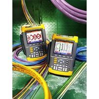
Fluke 225C Color ScopeMeter with Industrial Bus Health Test capability
Parameters are automatically qualified as ‘good’, ‘weak’ or ‘bad’ based on a comparison to the appropriate industrial standards or to user set reference values. Each of the measured parameters is presented with momentary value and with statistical minimum and maximum values measured over time. The reference values used are also displayed, to give the user an easier grip on the systems behavior. Tested parameters include signal amplitudes, bias voltage, rise- and fall-times, jitter, distortion and noise levels (in-band noise as well as out-of-band noise) depending on the requirements of the associated industry standard.
Active Questions & AnswersAsk a Question
There are no current Discussions
Oscilloscopes Service ProvidersView All (2)
Documents & Manuals
There are no Documents or Manuals available.
Features of ScopeMeter® 225C
Bus Health Test Bus Health Test analyses the electrical signals on the industrial bus or network and gives a clear “Good, “Weak or “Bad validation mark for each of the relevant parameters, presented next to the actual measurement value. Measured values are compared to standard values based on the selected bus type, or you may set your personal reference values if you need different tolerances.
All common bus types are supported The 225C ScopeMeter support not just one or two bus systems but all commonly seen industrial buses. From the lower speed AS-i and CAN to the higher speed Ethernet 100Base-T based systems are covered by a single instrument. A simple menu structure allows for selecting the main bus type and, where applicable, sub-types listed in a sub-menu for easy selection. Tested parameters and reference values are then set according the selection made.
Large color screen The large color screen of the 225C shows the individual parameters with validation, the actual measured value, the minimum and maximum values recorded over time, and the reference values used for the validation. The choice of parameters differs with the bus type and may include bias voltage, signal high- and low-levels, rise- and fall-times, in-band and out-of-band noise levels, jitter, pulse width, baud rate, and more. The activity indicators tell you the data ?ow is ongoing and they stop ?ashing the moment communications come to a halt.
Making test connections The large screen also gives wiring information for each of the supported bus types, giving the user guidance in making the test connections. A set of break-out adapters is included with the 225C to give access to each of the wires and pins of the commonly used connection systems M12, DB-9 and RJ-45.
Eye-pattern Mode The Fluke 225C can make the signal quality validation as soon as electrical signals are passed along the network, without looking at the data content. They find errors like improper cable connections, bad contacts, incorrect grounding and missing or superfluous terminators. In the eye-pattern mode, a waveform display is built over successive signal passes to give you a visual indication of overall signal quality, noise levels and signal jitter, using the scope’s user selectable persistence mode.
Floating independently isolated input channels Thanks to the independently isolated input channels and the floating inputs, the ScopeMeter can take truly floating differential measurements from balanced 2-wire systems such as RS-485 and CAN, giving a high level of suppression for common mode disturbances and noise. One input channel can be connected to measure the voltage between the two signal wires, and the other can be connected to measure the common mode voltage over ground at the same time, independently. This way, you may also measure the signals passing through the twisted wires of the 100Base-T Ethernet.
General Specifications
There are no General Specifications available.